Multifunction shields
In the process of developing simple tutorial sessions for use of the XOD graphical programming environment, and control of Arduino-driven hardware - we have explored the use of multifunction shields to simplify the training session - to minimise fiddly and error-prone wiring during the sessions. The use of these shields can introduce clashes between their onboard devices and elements on the Rich UNO R3. Details of the Multifunction shields and their required ports are shown below.
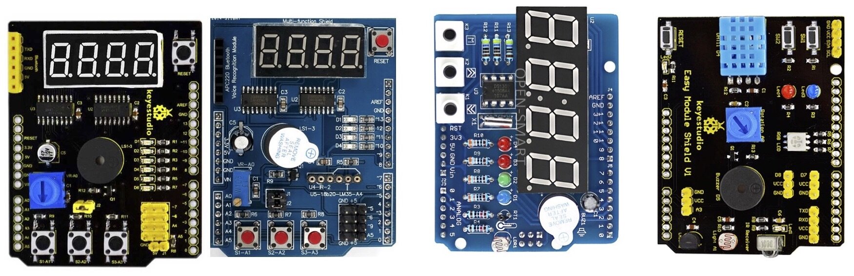
Shown above: Keyestudio Multi-Function shield V2 (£7.50), HAILANGNIAO Multi-Function shield V2 (£1.40), Open-Smart RTC shield (£8.00) and Keyestudio Multi-purpose shield V1 (£7.50). Each shield bears a range of components accessing a variety of Arduino ports (listed above. Some of these clash with ports already used on the Protoshield Plus. Happily, it is simple to rewire the ports. We suggest making the following changes to the default settings of the board.

Suppliers of multifunction boards:
Keyestudio Multipurpose Shield V1: https://www.keyestudio.com/products/free-shippingkeyestudio-multi-purpose-shield-v1-for-arduino-starter
More technical details at: http://wiki.keyestudio.com/index.php/Ks0183_keyestudio_Multi-purpose_Shield_V1
Keyestudio Multi-Function shield V2: https://www.keyestudio.com/products/free-shipping-keyestudio-multi-purpose-shield-v2-w-gift-box-for-arduino-starter
More technical details at: http://wiki.keyestudio.com/index.php/Ks0184_keyestudio_Multi-purpose_Shield_V2
HAILANGNIAO Multi-Function shield V2: https://www.aliexpress.com/item/Multifunctional-expansion-board-kit-based-learning-for-UNO-r3-LENARDO-mega-2560-Shield/32845170467.html
Open-Smart RTC shield: https://www.aliexpress.com/item/For-Arduino-Expansion-Board-Clock-Shield-Wire-Digital-Module-SCM-Experiment-Original-Product-Blue-Black/1771823374.html
HAILANGNIAO Multi-Function shield V2
The next part of the description focuses on the availability and use of low cost, high precision sensors that can be easily used for scientific purposes. We will also introduce the use of a second multi-function shield that will provide some useful features for the use of sensors. The shield contains:
4 digit 7-segment LED display module (3641BH) driven by two serial 74HC595’s (Pin Latch 4, Clock 7, Data 8)
4 Red LEDs (Pin 10,11,12,13) [D1-13, D2-12, D3-11,D4-10]
10K potentiometer (Pin A0) [Vr-A0]
3 x push buttons (Pin A1, A2, A3) [S1-A1, S2-A2, S3-A3]
Piezo buzzer (Pin 3 digital ON/OFF) [LS1-3]
DS18B20 temperature sensor interface (not included) (Pin A4) [U5-18b20-LM35-A4]
Infrared receiver interface (Pin 2) [U4-IR-2] Compatible to a 1838B Infrared IR receiver
Bluetooth interface (GND, +5v, 0 = tx, 1 = rx) [APC220]
Free pins pwm (5, 6, 9, A5) with GND, +5V
Serial interface header for connection to (optional) serial modules (Bluetooth, wireless interface, voice module, a voice recognition module)
The Hackatronics section of the Cohesive Computing site (http://www.cohesivecomputing.co.uk/hackatronics/) provides an excellent source of information about this shield, along with Arduino IDE code to drive features of the board. Support for XOD, a relatively new platform, is less well developed, but growing rapidly. Our tireless Biomaker support crew have produced custom nodes and patches to help exploit the shield.
3. Triggering the buzzer
We have compiled a XOD library that contains nodes and patches that you can use to provide audible output. The buzzer on the shield can be triggered to produce timed output of defined frequency (tone). A transistor is used to control the piezo speaker (LS1) - which is activated when the output port D3 is set to zero (Unlike the buzzer on the Multi Purpose shield used in Training Session 1 & 2, there is no need to drive a oscillating signal through LS1, it is set automatically).
4. LED 7-segment display
The tutorial library for training session TWO also contains support for other components on the shield, including switches 1 (port A1), 2 (port A2) and 3 (port A3); the variable resistor (port A0) and bank of 4 red LEDS (ports D1-D4).
In addition, the shield has a 4 digit 7-segment LED display. The digits are made up of seven individual LED segments, which must be controlled to form particular numbers.
Controlling individual LED segments to display numerical values.
The shield is wired with two 74HC595 shift register chips that each take an 8-bit serial input and decodes this to provide 8 parallel outputs. Suitable serial codes are sent to the circuit to control the display of numbers on the display. Marco Aita has wrangled code that allows the circuit to be used inside the XOD environment (with thanks to Arduino Learning).
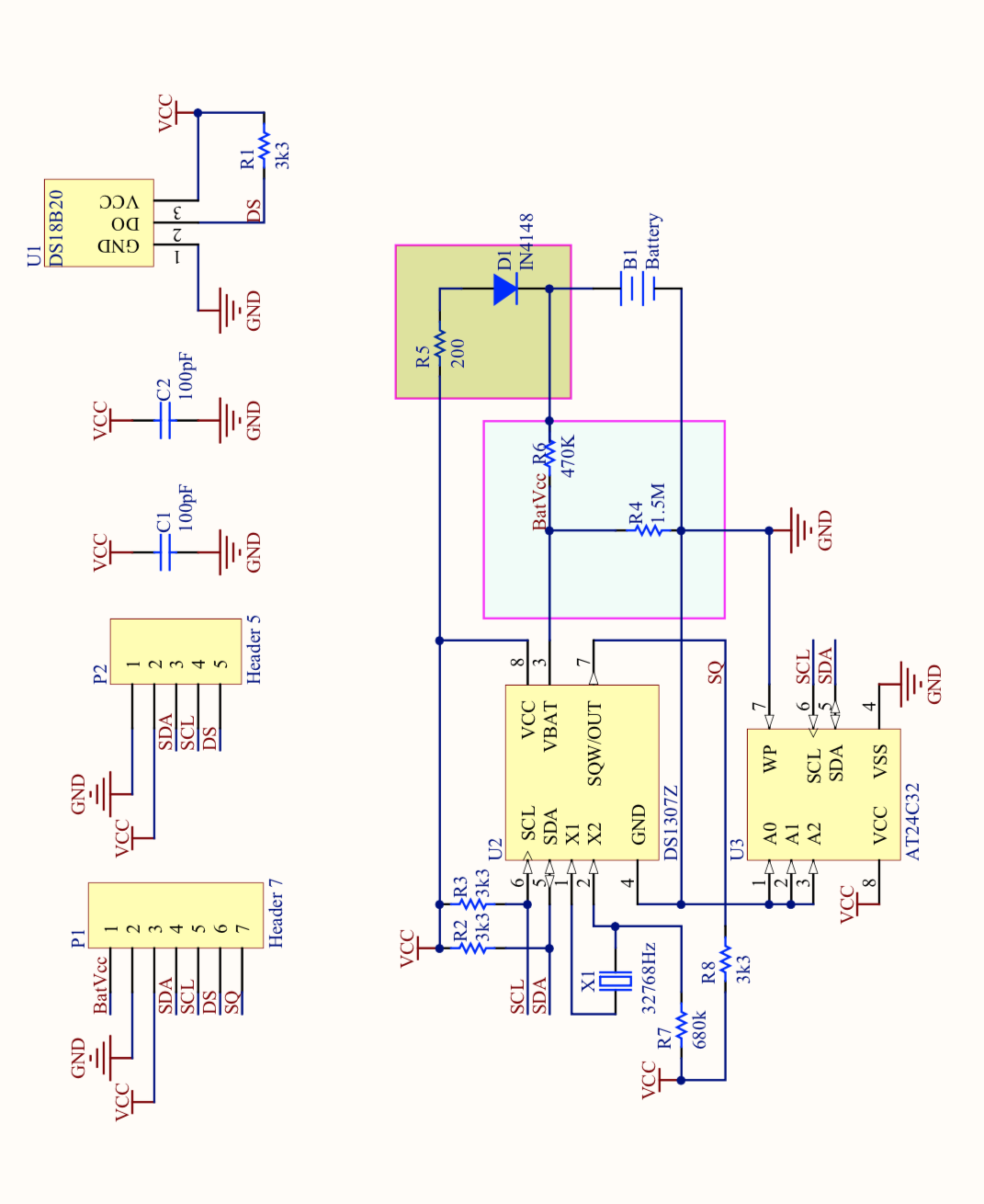
5. Real time clock
I2C Tiny RTC DS1307 Real Time Clock Module AT24C32 Board for Arduino (Battery included)
Two wire I2C interface
Hour : Minutes : Seconds AM/PM
Day Month, Date - Year
Size: 28x25x10mm
Leap year compensation
Accurate calendar up to year 2100
1Hz output pin
56 Bytes of Non-volatile memory available to user
DS1307 is a low-power real-time clock chip with 56 bytes of non-volatile RAM, full BCD code clock and calendar. The address and data will be transmitted via a two-wire bidirectional serial bus, and the chip can provide information such as seconds, minutes, hours, etc., and the number of days in each month can be automatically adjusted. Besides, there is a compensation function for leap year. AM / PM flag is to determine whether the clock operates in 24-hour or 12-hour mode, and there is a built-in power-sense circuit in the chip with powering down detecting and battery switching functions.
6. DS18B20 temperature sensor
The new shield provides support for the DS18B20 digital thermometer chip. Note that Jumper one (J1) must be added to allow the sensor to work.
DS18B20 digital temperature sensor adopts single-bus technology, which can effectively reduce external interference and improve the measurement accuracy. Meanwhile, it can convert the measured temperature directly into a serial digital signal for computer to process. With simple interface, it makes data transmission and processing much easier.
7. Additional I2C sensors
1-Wire and I2C are true shared-bus protocols - you can have 100+ components all talking at once using the same 2 wires (for I2C) or a single for 1-Wire. I2C (Inter-Integrated Circuit) is a faster and more open standard, and many sophisticated (and often cheap) digital devices are available for connection.
List of I2C devices and addresses compiled by Adafruit
XOD provides a series of I2C primitives that can be combined to create custom patches and nodes.
Download software library
The starter code for Tutorial Session Three can be downloaded. Marco Aita has compiled a series of patches and nodes for this training session, which can be obtained from: https://biomaker.squarespace.com/s/TutorialThree_Archive.zip
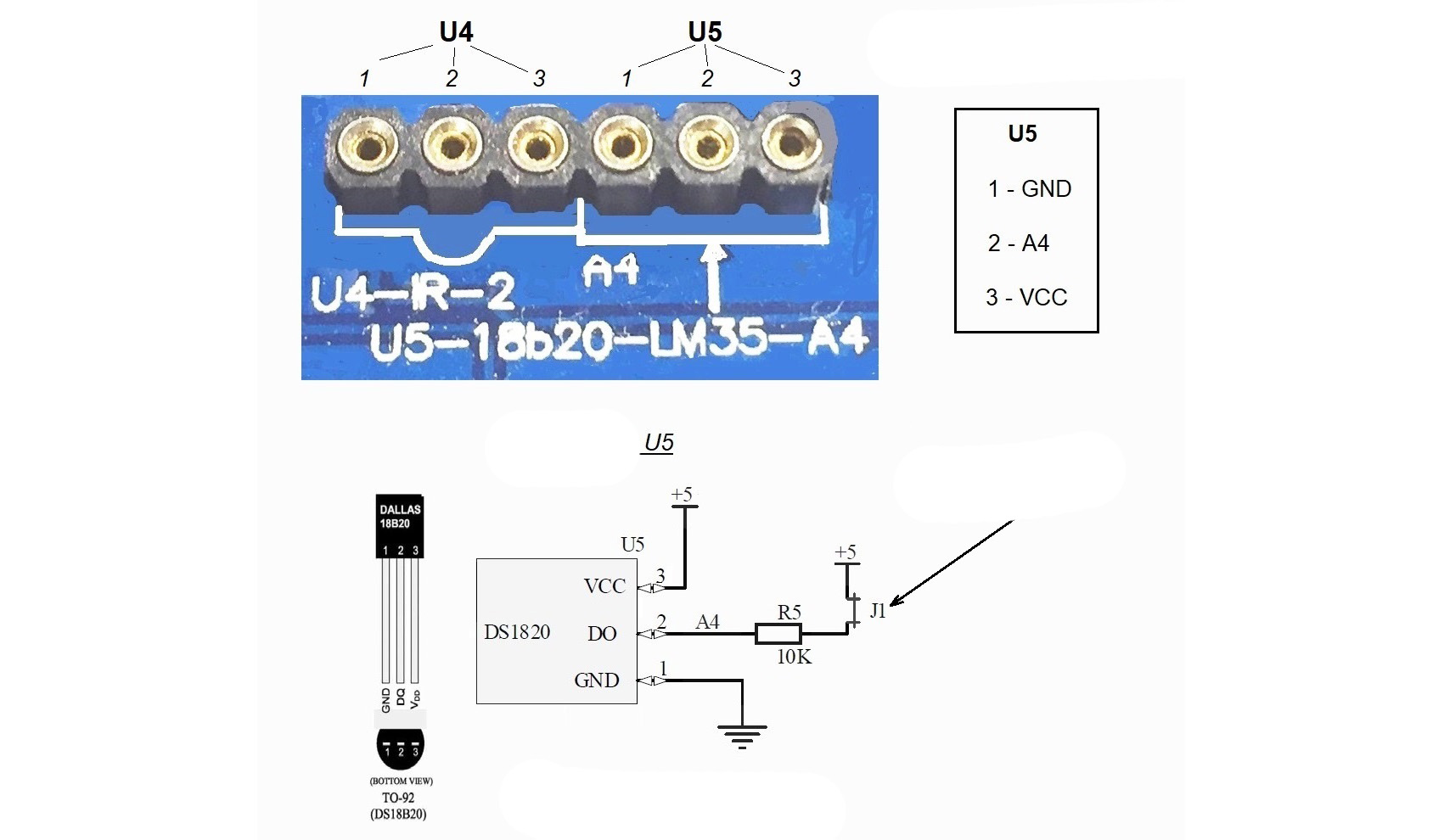
Connecting the GND (black), A4 data (yellow) and VCC 5V (red) wires of the DS18B20 device to the multi function shield.


Multi-function shield II

Buzzer circuit

Real time clock module, with battery backup

Waterproof, sealed cables containing DS18B20 temperature sensors
Reference materials

Circuit diagram for the Multi-function shield II board (1 page PDF, 24KB)

Data sheet for DS18B20 1-wire digital thermometer (22 page PDF, 262 KB)
Link to Hackatronics description of the multi-function shield with the Arduino IDE and libraries (30 page PDF, 383 KB)