
Establishing 3D Printed Microfluidics for Molecular Biology Workflows
This project is developing low-cost lab-on-a-chip microfluidics sultions for plant molecular biology, and follows on from the SynBio SRI Fund project "Plant Pro-Chip"
The Idea
The basic tools of a molecular biologist have changed little since the early 1990s; procedures tend to be performed manually and involve the use of large volumes meaning progress is slow and low throughput. These factors become problematic as research begins to move into the era of whole genome engineering. Over the last decade there have been significant advances in the field of microfluidics leading to the production of lab-on-chip devices, but the downside of these approaches is that they tend to rely on expensive, specialist equipment, meaning they are out of reach to most molecular biology laboratories. Several recent publications have begun to address this issue, utilizing advances in 3D printing to create low cost alternatives. By utilizing expertise in Cambridge and the NBI (Norwich Biosciences Institutes), the aim of this proposal is to design and test a 3D printed, modular microfluidic setup for molecular biology. All designs will be documented and open access, and, by instigating a standard for modular microfluidics, the outputs can serve as a basis for further innovation.
The Team


Dr Steven Burgess,
Postdoctoral Researcher, Department of Plant Sciences, University of Cambridge
Dr Tom Meany,
Postdoctoral Researcher, Department of Plant Sciences, University of Cambridge
Dr Richard Bowman,
Postdoctoral Researcher, Department of Physics, University of Cambridge
Dr Oleg Raitskin,
Postdoctoral Researcher, The Earlham Institute, Norwich
Dr Neil Pearson,
Postdoctoral Researcher, The Earlham Institute, Norwich
Project Outputs

Project Report
Summary of the project's achievements and future plans

Project Proposal
Original proposal and application

Project Resources
Establishing Low Cost Microfluidic System for Single Cell Analysis
Part A: Producing a Syringe Pump

Initial design: Schematic of proposed microfluidic device
The first iteration of a syringe pump was produced and assembled following the open source design from (Patrick et al., 2016; Figures 1-4). Arduino control of the A4988 Stepper Motor Driver Module (#02258664) was step up following instructions adapted from this tutorial and performed as expected. For wiring diagram see Figure 3. Arduino Stepper Motor Script can be found in the project report. Testing of the syringe pump design identified several limitations:
The use of a flexible connector to couple the motor and rod resulted in vibrations. This became a problem at small motor step sizes in the motor as the vibrations meant the resulting noise interfered with smooth operation of the pump. Potential solution: replace connector with rigid alternative.
The method of syringe attachment to the pump was a major flaw. Two problems arose – (1) by printing a fixed groove size for the syringe holder, operation is limited to only BD 1ml Plastipak syringes, this was an issue when switching the 1ml Luer-Lok syringes which did not fit. (2) The fitting was too loose, such that when under pressure syringes were wont to jump out of the device. Potential solution: requires re-design of the syringe casing including adjustable attachment rings to hold syringes in place. Alternatively to switch to a different alternative open source design (Wijnen et al., 2014), or use a solenoid pump.
Oscillating flow. As foreseen in the proposal the stepper motor was insufficiently smooth in operation. The effect of stepping introduced highly variable droplet size in preliminary experiments.
Controlling Flow Rates: It became apparent that separate regulation of flowrates for carrier fluids (oil) and buffers are highly desirable to control droplet size. Potential solution: use multiple syringe pumps, or a solenoid pump.
PART A Components:
- 1x5/6/6.35/8mm Flexible Shaft Coupling Motor Connector
- 8mm Lead Screw Rod Z Axis Linear Rail Bar Shaft 150mm +Nut T8
- Nema 17 3D Printer CNC Twophase 4 wire Stepper Motor 1.8Deg 17HD3400822B
- A4988 StepStick Stepper Motor Driver
- Male-Male breadboard connectors
- HeroNeo® 5pcs Easy Connectors For Led Strip Light 3528 5050 to link Adapter Power Supply
- Arduino Uno
- Laptop
- USB Connector
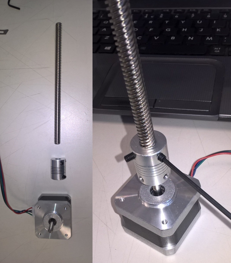
Figure 1: Syringe Pump Motor Assembly

Figure 2: 3D Printed Syringe Pump Assembly
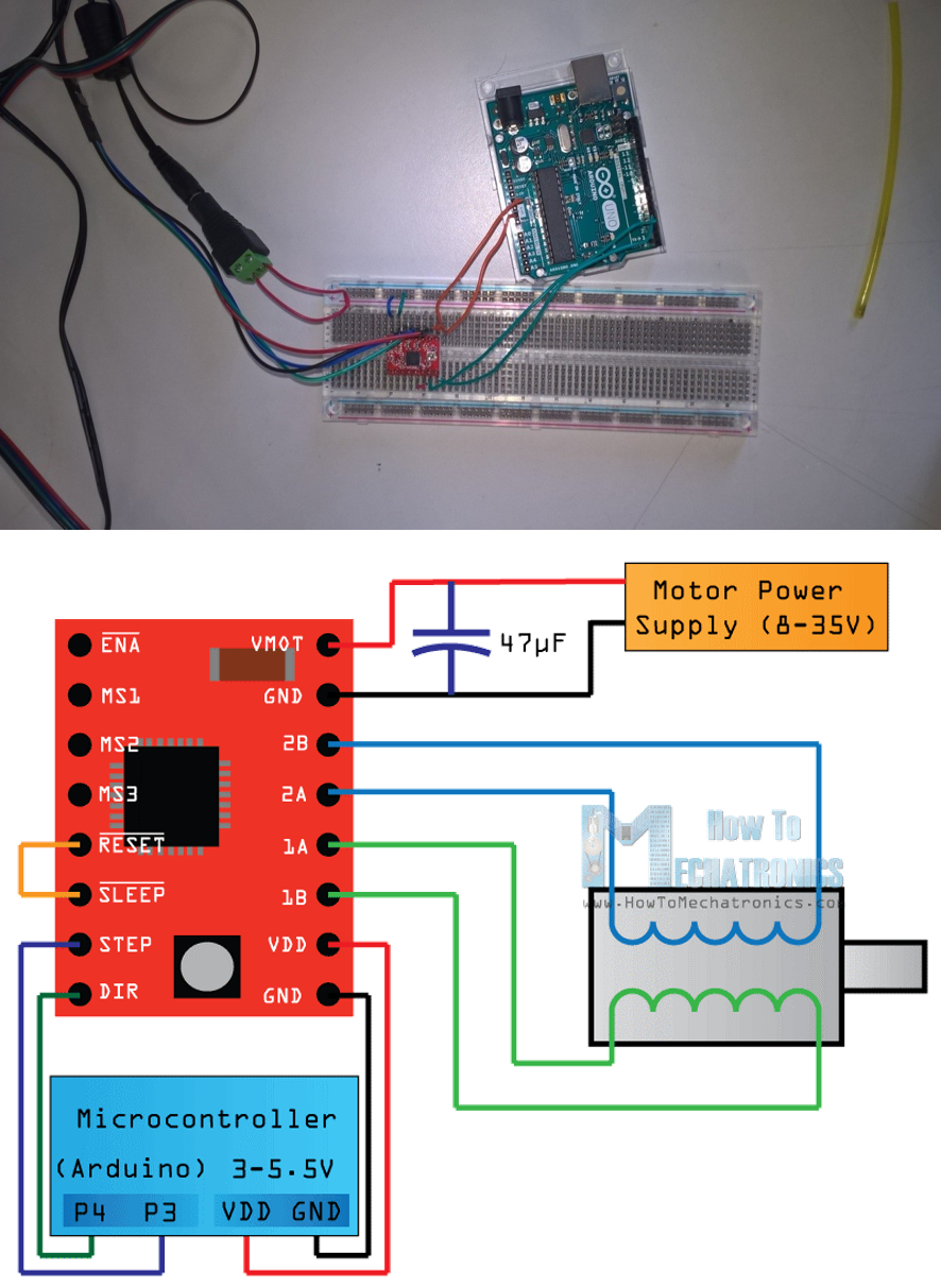
Figure 3: A4988 Stepper Motor Driver Module wiring diagram. Source: Dejan Nedelkovski.

Figure 4: Final assembly of the Syringe Pump with 1ml BD Plastipak syringes attached.
Part B: Producing a Droplet Generator
A prototype microfluidic chip was produced by cutting 5mm acrylic sheets with a LS 6090 PRO Laser Cutter powered by a 60w CO2 Water Cooled Laser Tube in Cambridge makespace. Each prototype chip consisted of two components: a bottom piece with channels cut in a cross junction for mixing of oil and water, and a top cover to seal the channel with holes cut for insertion of tubing (Figure 5). The channel width generated by the laser was ~300µm. Testing identified the following limitations:
Leakage from tube to chip connections: Inaccuracies in cutting holes for tubing into the top piece of the chip resulted in leaking. Bluetack was unable to provide a proper seal (Figure 7), but this was remedied with the addition of superglue (Figure 8).
Leakage between upper and lower pieces of the chip: Three approaches were attempted to hold the upper and lower pieces of acrylic together: neodymium magnets, steel clips (Figure 7) or superglue. All proved ineffective in preventing leakage of liquid out of the microfluidic channels on the lower surface into the interface between the two sheets of plastic (Figure 9). This is presumed to be the result of slight warping on the plastic sheets preventing a tight seal. To address this issue a plastic coating was attached over the lower part of the chip prior to clamping with the top surface to hold the tubes in place. Using this setup it was possible to contain the carrier and buffer liquids within the microfluidic channels and produce water in oil droplets when connected to syringe pump.
Due to the numerous difficulties encountered in the use of laser cut chips, which were also restricted by the lower limit of channel width (~300µm), and roughness of channels cut it was decided to test a capillary system using commercial components.
A 360µm T-junction with 150µm internal diameter was used in combination with 1ml Luer-Lok syringes (Figure 11). This addressed any issue of leaks, and provides a standardized small channel diameter. Full prototyping of the T-junction was prevented by issues relating to the syringe pump – (1) the syringes did not fit to the pump, so where held in place by tape (2) pressure build up on the line from the carrier phase resulted in buckling of the syringe when held in place with tape (3) the requirement for variable flow control over carrier and solute components to facilitate droplet production.
Part B Components:
- PEEK Tubing 360μm (Kinesis;1572)
- MicroTee Assay PEEK 360μm (Kinesis;P-888)
- Luer Lock Connector (VWR; P-662)
- Luer Lock Syringes (Fisher;10630694)

Figure 5: Prototype laser cut microfluidic chip, showing bottom and top pieces of 5mm acrylic cut separately and assembled with tubing (left to right).

Figure 6: Prototype laser cut microfluidic chip (detail). 4x objective image showing channel width (~300μm) and cross junction.

Figure 10: Prototype microfluidic chip. (Right) Liquid contained within channels when plastic cover placed between top and bottom acrylic components. (Left) Water in oil droplets produced from chip.

Figure 7: Prototype laser cut microfluidic chip held together by steel clamps. Showing attempt to seal wires with Bluetack (right) and the resulting leak (left).

Figure 8: Superglue seal of tubing to laser cut microfluidic chip

Figure 9: Prototype Microfluidic chip, leakage of liquid between top and bottom components when sealed with superglue.

Figure 11: Capillary droplet generator