
Programming robots and actuators
The mBot
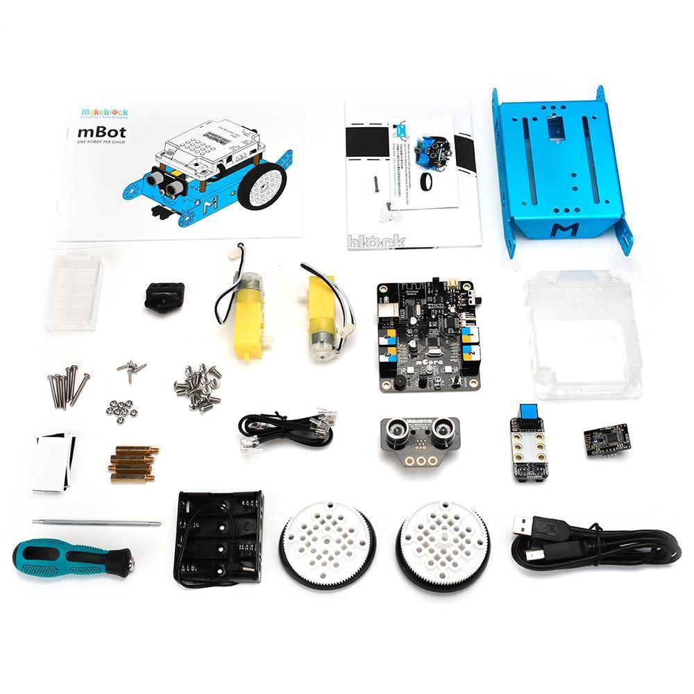
The robot consists of: Arduino UNO compatible main control board; Light Sensor, Me Ultrasonic Sensor, Me Line Follower Sensor; Bluetooth/USB communication ports
1.5V AA Batteries*4 power supply
170 * 130 *90mm(L*W*H)1034g.
The basic chassis has two electric motors that individually power its wheels, with ultrasonic sonar sensor for distance measurement and infrared sensors for line tracking. However, the chassis allows mounting of additional sensors and actuators.
More details at: https://www.makeblock.com/steam-kits/mbot
Instructional youtube videos: click here


mCore board
Arduino ports for onboard devices
Light sensor A6
Buzzer: D8
Button: A7
2x Neopixel RGB LEDS D13
Motor 1: D6, D7
Motor 2: D4, D5
IR emitter: D3
IR receiver: D2
The board also has solder points for ports A0-3, D9-12 and I2C SDA,SCL
1. Assemble the robot
The mBot devices are provided as a kit with full assembly instructions. Please assemble. This should take around 20-30 minutes. A PDF version of the instruction manual can be found at the following link:

The robots can be controlled using the provided IR controller, Bluetooth or programmed via XOD, using the USB port. When it is first turned on, the mBot has 3 pre-set control modes: Obstacle avoidance mode, Line-follow mode, and Manual control mode. These can be switched using the IR controller or button on the robot (details in the manual), and used to test the device after assembly.
mBot downloads
Before you can connect your mBot to your PC, Mac or mobile device, you need to install the mBot USB drivers. The mBot manufacturers have provided a range of programming tools that can be used with the robot: https://mblock.makeblock.com/en-us/download/. Installing the MakeBlock software packages also provides access to the USB drivers - and this may the simplest way to get up and running. This will also provide an alternative programming platform to explore.


Alternatively, drivers for the CH340/341 USB-serial chip can be found online
Troubleshooting guide for mBot: https://www.vernier.com/til/4136/
Mac drivers: http://download.makeblock.com/mblock/CH34x_Install_V1.3.pkg
Cheat Sheet: https://forum.makeblock.com/t/cheat-sheet-getting-started-mbot-more/2960
2. XOD PID controller for the mBot
Max Danilin (https://twitter.com/gabbapeople) has created some excellent tutorials for the use of XOD with the MakeBlock mBot. In one, he describes the use of the XOD pid-controller node to control self-navigation of the mBot. (A proportional–integral–derivative controller or PID-controller is a control loop feedback mechanism used in automatic control systems to maintain the value of the measured parameter.)
https://medium.com/xodlang/how-to-program-mbot-with-xod-pid-controller-c3e310f8eceb
The article describes control of the mBot - including (i) an mbot-motors node to drive robot movement, (ii) an mbot-ultrasonic-sensor node that calculates the distance to obstacles from the mBot ultrasonic sensor. These are connected to the XOD pid-controller node.
The PID controller calculates an “error” value as the difference between a measured input value and the desired setpoint. The controller attempts to minimize the error by adjusting the output. To control the output, a PID-controller uses coefficients Kp, Ki, and Kd which are based on error changes.
The PID controller will be set with a target value or set point - and provided with a measured value.

You will need to Kp pin = proportional factor. Coefficient Kp is proportional to the current value of error.
Ki pin = integral factor. This coefficient is used to neutralize the accumulating part of the error. It can eliminate system errors accumulate after a certain amount of algorithm loops.
Kd pin = derivative factor. It estimates the trend of future errors using Kd rate of change. The more rapidly the rate of error changes, the higher the controlling or dampening effect of PID-controller will be.
There are no specific values of Kp, Ki, Kd coefficients. Different systems with a PID-controller will have individually tuned ratios.
Exercise 1:
Set up the mBot to approach an obstacle and remain at a fixed distance. Experiment with PID parameters. Add basic navigation routines and collision avoidance.
XOD library for tutorial session
A .xodball library of XOD code for the tutorials can be downloaded here.
(You will need to pay attention to the ports used for your circuit - and to match these with the XOD programme).


Kp = 5

Kp = 90

Kp = 40

Kd = 0

Kd = 10
3. mBot navigation and line following
The mBot comes with dual infrared emitter-sensors that are mounted in the front of the robot - to allow line-following. The use of these are described in Max Danilin's second tutorial article.
The sensors are connected to one of the mBots RJ25 ports. The bot-line-sensor node communicates with the hardware through the S1 and S2 input pins. It has two output pins L and R according to the left and right infrared sensor on the board. True value on an output pin means that there is a white or bright color in front of the infrared sensor. In turn, false value means that the color is black or dark.


Situation 1. Both IR LEDs are on the line. mbot-line-sensor node puts false to the L and R pins. mBot should move forward.
Situation 2. The left IR LED is on the line while the right deviates to the right. mbot-line-sensor node puts false to the L pin, and true to the R. mBot should turn to the left.
Situation 3. The right IR LED is on the line while the left deviates to the left. mbot-line-sensor node puts true to the L pin, and false to the R. mBot should turn to the right.
Situation 4. Both IR LEDs are out of the line. mbot-line-sensor node outputs two true values. mBot should turn around to find the missing line.
A PID-controller requires a single variable input while the mbot-line-sensor outputs two. To solve this problem, subtract node is added. This node subtracts two boolean variables and produces a number. In this way, the subtract node can output the values:
0 for the first situation;
-1 for the second situation;
1 for the third situation;
0 for the fourth situation.
We use those four situations to form the “error” concept for the PID-controller. The situation when the incoming value is 0 and both IR LEDs are in line is ideal for us. That’s why we should set up the the TARG pin to 0.
But this patch in its form can work correctly only with the second and third situations. When mBot completely loses the line the incoming value for the pid-controller node will be 0 too. For this case special logic needs to be introduced, which is explained in detail at:
https://medium.com/xodlang/xod-powered-line-follower-mbot-2ae4a4862a9e


Ki = 2
Images from: Max Danilin, https://medium.com/@gpeople
Self-balancing robot
Additional article on building a modified, self- balancing mBot with accelerometer and XOD software also from Max Danilin. Extensive testing and description of PID controller parameters can be found at: https://medium.com/xodlang/xod-and-pid-powered-self-balancing-mbot-6c420600271e

Challenges:
The mBot is equipped with a range of peripheral devices - can include these in any of your programmes - for example to provide collision warnings or feedback?
A0 RJ25 plug 4 (default not-connected)
A1 RJ25 plug 4 (default not-connected)
A2 RJ25 plug 3 ultrasonic
A3 RJ25 plug 3 ultrasonic
A6 light sensor
A7 button
D2 IR RCV
D3 IR TX
D4 DIR2 - direction motor2
D5 PWM2 - pwm motor2
D6 PWM1 - pwn motor1
D7 DIR1 - direction motor1
D8 buzzer
D9 RJ25 plug 2 linefollower
D10 RJ25 plug 2 linefollower
D11 RJ25 plug 1 (default not-connected)
D12 RJ25 plug 1 (default not-connected)
D13 2 WS2812 Neopixel RGB LEDs
The board also has solder points for ports A0-3, D9-12 and I2C SDA,SCL, so additional components could be added to the robots.Can you engineer robot-robot sensing and communication?
More details about mBot ports at: http://blog.hmpg.net/2016/04/makeblock-mcore-information.html
Additional resources:
XOD libraries for the mBOT: https://xod.io/libs/gabbapeople/mbot-lib/ (gabbapeople/mbot-lib loaded in XOD)
We've collected the relevant code from the gabbapeople/mbot-lib library and placed it in the tutorial session code.
MakeBlock downloads for mBot series: https://www.makeblock.com/steam-kits/mbot-2
(Instructions, videos, schematics, etc.)
MakeBlock programming information for the mBot: http://learn.makeblock.com/en/mbot-programming/
Thingiverse 3D printed accessories for mBot: https://www.thingiverse.com/tag:mbot
(Including brackets, pen holders, bumpers, etc.)
Collection of mBlock pseudo-code for controlling the mBot: http://www.mblock.cc/example/introduction/
(includes control of mCore onboard LEDs, sensors, etc.)
MakeBlock Github site: https://github.com/Makeblock-official
PID Controller Basics Using XOD and Arduino: https://medium.com/@victoriandeolrn/pid-controller-basics-using-xod-and-arduino-d1eb604b46d

Circuit diagram for the mCore control board of the mBot
Programme logic for obstacle avoidance
Programme logic for line follower

Programming robots and actuators
mBot servo extension pack
Makeblock offers extension kits for the Arduino UNO compatible mBOT. As well as the main control board; Light Sensor, Me Ultrasonic Sensor, Me Line Follower Sensor; Bluetooth/USB communication ports, the servo extension pack provides the Me RGB LED, Me RJ25 adapter and 9g Micro Servo, along with hardware mounting components.
The extension kit allows the construction of modified robots - shown right.
More details at: https://www.makeblock.com/steam-kits/mbot

mCore board
Arduino ports for onboard devices
Light sensor A6
Buzzer: D8
Button: A7
2x Neopixel RGB LEDS D13
Motor 1: D6, D7
Motor 2: D4, D5
IR emitter: D3
IR receiver: D2
The board also has solder points for ports A0-3, D9-12 and I2C SDA,SCL
Servo extension pack:
Me RGB LED
Me RJ25 adapter
9g Micro Servo+ mounting kit
Technical information:

Click here to download the instruction manual for the mBot Servo Extension Kit (PDF 3.7 MB)
Click here to download 9g Micro Servo information sheet
Click here for link to Core CPU Board information
Click here for link to RGB LED module information
Click here for link to Me RJ25 Adapter information
Click here for link to 9g Micro Servo Kit information
Tutorials for using XOD with servos:
Click here for link to Official XOD.io tutorial
Click here for link to servo control via potentiometer
Click here for link to XOD Tutorials about:
Create a Self-Driving Robot — Part One
Advanced Motor Control — Part Two
Servo control - Part ThreeHacking Nodes with C++ — Part Four
(From Tommy Warner, Medium)
Video tutorials:
XOD control of servos
Don't forget:
Before you can connect your mBot to your PC, Mac or mobile device, you need to install the mBot USB drivers. The mBot manufacturers have provided a range of programming tools that can be used with the robot: https://mblock.makeblock.com/en-us/download/. Installing the MakeBlock software packages also provides access to the USB drivers - and this may the simplest way to get up and running. This will also provide an alternative programming platform to explore.
Alternatively, drivers for the CH340/341 USB-serial chip can be found online
Troubleshooting guide for mBot: https://www.vernier.com/til/4136/
Mac drivers: http://download.makeblock.com/mblock/CH34x_Install_V1.3.pkg
Cheat Sheet: https://forum.makeblock.com/t/cheat-sheet-getting-started-mbot-more/2960
Challenges:
The mBot is equipped with a range of peripheral devices - can include these in any of your programmes - for example to provide collision warnings or feedback?
A0 RJ25 plug 4 (default not-connected)
A1 RJ25 plug 4 (default not-connected)
A2 RJ25 plug 3 ultrasonic
A3 RJ25 plug 3 ultrasonic
A6 light sensor
A7 button
D2 IR RCV
D3 IR TX
D4 DIR2 - direction motor2
D5 PWM2 - pwm motor2
D6 PWM1 - pwn motor1
D7 DIR1 - direction motor1
D8 buzzer
D9 RJ25 plug 2 linefollower
D10 RJ25 plug 2 linefollower
D11 RJ25 plug 1 (default not-connected)
D12 RJ25 plug 1 (default not-connected)
D13 2 WS2812 Neopixel RGB LEDs
The board also has solder points for ports A0-3, D9-12 and I2C SDA,SCL, so additional components could be added to the robots.Can you engineer robot-robot sensing and communication?
More details about mBot ports at: http://blog.hmpg.net/2016/04/makeblock-mcore-information.html
Additional resources:
XOD tutorial: How to control a servo: https://xod.io/docs/tutorial/11-servo/
XOD library for the mBOT: https://xod.io/libs/gabbapeople/mbot-lib/ (gabbapeople/mbot-lib to be loaded in XOD)
XOD library for servos: https://xod.io/libs/gweimer/servo/ (gweimer/servo to be loaded in XOD)
Enhanced servo implementations to detach servo and allow it to free-wheel (or allow other nodes to control the servo)
MakeBlock downloads for mBot series: https://www.makeblock.com/steam-kits/mbot-2
(Instructions, videos, schematics, etc.)
MakeBlock programming information for the mBot: http://learn.makeblock.com/en/mbot-programming/
Thingiverse 3D printed accessories for mBot: https://www.thingiverse.com/tag:mbot
(Including brackets, pen holders, bumpers, etc.)
Collection of mBlock pseudo-code for controlling the mBot: http://www.mblock.cc/example/introduction/
(includes control of mCore onboard LEDs, sensors, etc.)
MakeBlock Github site: https://github.com/Makeblock-official
PID Controller Basics Using XOD and Arduino: https://medium.com/@victoriandeolrn/pid-controller-basics-using-xod-and-arduino-d1eb604b46d
Alternative programming applications for mBot:
Find details and links for downloading mBlock, MakeBlock, mBlock Blockly
Circuit diagrams:

Makeblock mBot ultrasonic rangefinder circuit

Makeblock mBot line follower circuit

Makeblock RJ25 adapter board circuit
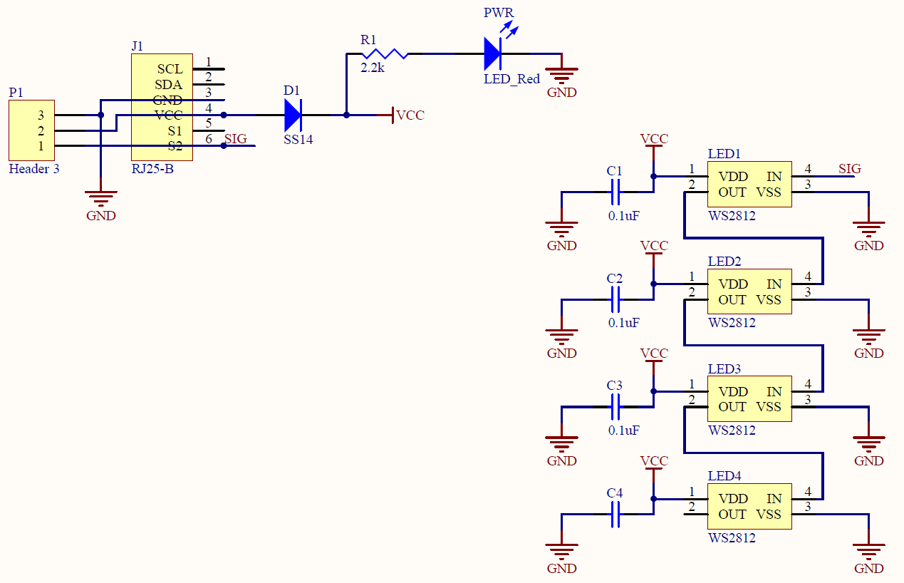
Makeblock RGB LED module circuit