
How to build new touchscreen-based user interfaces
The Biomaker Arduino starter kit contains a 4D Systems touchscreen display. The LCD display can be hooked up to the Arduino via a serial port. It is now possible to build sophisticated user interfaces for Arduino-based instrumentation using graphical tools. Here’s a guide for how to go about this:
A. Program the touchscreen display
Plan your scheme for hardware connections and lay out a draft of the onscreen indicators and control elements that you want to use.
Load the 4D Systems IDE on a Windows PC, or Windows emulator on a Mac (Parallels works well). The software environment provides ViSi-Genie, a wysiwyg tool for layout of user interface tools.
ViSi-Genie provides a wide range of interactive user interface elements for display of gauges, meters, indicators and input devices such as switches, knobs, sliders and buttons.
After laying out the screen display, (i) the interactive code can be downloaded to the flash memory in the programmable display via a 4DS adapter, and (ii) the graphical elements can be downloaded directly to a µSD memory card that plugs into the display.
B. Build interaction between the Arduino hardware and the customised display
There is now a XOD library that allows graphical programming of Arduino hardware for two-way communication with screen graphical elements through a serial port.
Use the XOD graphical programming environment to build interactions between the Arduino-connected hardware and screen widgets.
Test interaction between the Arduino hardware and 4DS touchscreen through the XOD development environment.
A. Programming the touchscreen display
The Biomaker Arduino starter kit contains a 4D Systems uLCD-32DT-AR Arduino Display Module Pack, which includes a Gen4 µLCD-32DT 3.2" LCD display with resistive touch, a 4D Arduino adaptor shield and 5 way interface cable. The LCD display can be hooked up to the Arduino via a serial port. It is possible to build sophisticated user interfaces for Arduino-based instrumentation using graphical tools.
The gen4-uLCD-32DT-AR has a comprehensive range of serial commands ready to be received from the Arduino, to draw primitives such as lines, rectangles, circles and text, displaying images, playing sound and logging data to uSD card. It can utilise the Arduino's UART Serial Port and a single Digital pin.
Step 1: Download the 4D Workshop programming environment from:
(https://www.4dsystems.com.au/product/4D_Workshop_4_IDE/downloads). The basic version is free.
4D Systems also provides a free Windows-compatible software environment for programming the touchscreen displays. Workshop4 includes four development environments, for the user to choose based on application requirements or user skill level. ViSi-Genie is an advanced environment that doesn't require any text-based coding, it is done automatically for you. The software provides a toolbar filled with graphical widgets. These can be simply dragged to lay out the prototype interface with the objects you want, set the events to drive them and the code is written for you automatically. ViSi-Genie provides the latest rapid development experience from 4D Systems.
ViSi-Genie
ViSi-Genie is a drag-and-drop rapid development tool for designing and building graphic user interface on 4D Labs processor-based displays. It provides an easy method for designing complex graphics user interface (GUI) applications without any coding. A simple GUI application to be ‘designed’ from scratch in literally seconds. ViSi-Genie does all the background coding, with no programming language to learn.
Pick and choose the relevant objects to place on a virtual display. The full animation of the objects is done under-the-hood, such as pressing a button or moving the thumb of the slider. Each object has parameters which can be set, and configurable events to animate and drive other objects or communicate with an external host. Simply place an object on the screen, position and size it to suit, set the parameters such as colour, range, text, and finally select the event you wish the object to be associated with, it is that simple. Objects are classified in three different groups:
INPUT OBJECTS, as a button or a keyboard,
OUTPUT OBJECTS, as a gauge or a meter, and
COMBINED OBJECTS or INPUT/OUTPUT OBJECTS, as a slider which acts as both an input and an output.
In seconds you can transform a blank display into a fully animated GUI with moving meters, animated press and release buttons, and much more. The assembled code can be directly downloaded to a 4D Systems display to check the screen display. (Note: compiled code is downloaded to the display ViSi-Genie, and stored graphic elements are separately downloaded to a µSD memory card in a semi-automated process). ViSi-Genie provides debugging tools to interrogate communication streams to/from the programmed display. The ViSi-Genie environment runs under Windows, but can be well implemented under Mac OS X using an emulator like Parallels.
4D Systems Application Note: Connecting a 4D display to an Arduino host
This application note shows how to create a ViSi Genie program and how to use the ViSi Genie library for the Arduino IDE. To achieve these objectives, a simple project is developed. This consists of a 4D Picaso module displaying six objects – a LED digits, a slider, a cool gauge, a string, a user LED, and a static text (label). To recreate the application described in this demo, the user first creates a ViSi Genie program in the 4D Workshop IDE and downloads it to a 4D display module. In this example, the Arduino host is programmed using the Arduino IDE. The Arduino and display communicate via a serial port. The Arduino programme loop must be configured to receive commands from interactive controls on the display, and to send relevant updates.
(https://www.4dsystems.com.au/appnote/4D-AN-00017/)
Technical resources:
4D Systems ViSi Genie User Guide
(https://www.4dsystems.com.au/productpages/ViSi-Genie/downloads/Visi-Genie_userguide_R_2_0.pdf)
4D Systems ViSi-Genie Reference Manual
(https://www.4dsystems.com.au/productpages/ViSi-Genie/downloads/Visi-Genie_refmanual_R_2_0.pdf)
Arduino IDE software library:
(https://github.com/4dsystems/ViSi-Genie-Arduino-Library)
Demonstration: This demo creates a touchscreen calculator
Code: (https://github.com/4dsystems/ViSi-Genie-Arduino-Demo-Calculator/)
Video: (http://www.youtube.com/watch?v=KFdDmTqGhK4)
Demonstration: This demo controls a tri-coloured LED along with displaying images from the SD card on the display in a slide show.
Code: https://github.com/4dsystems/ViSi-Genie-Arduino-Demo-Mood/
Arduino IDE software library:
4D Systems provides an Arduino IDE library that allows the use of programmed displays with Arduino boards programmed with the standard IDE.
(https://github.com/4dsystems/ViSi-Genie-Arduino-Library)
This IDE library provides high level functions for the Arduino, to simplify communication with 4D Systems modules when using a module configured with ViSi-Genie. Inside the library are 3 example sketches, to assist with getting started using this library. Inside is also a ViSi-Genie Workshop4 project, which can be used on a range of 4D Systems displays (designed for a uLCD-32PTU). It illustrates how to use some of the commands in the library include Read Object, Write Object, Reported Messages, Write Contrast and Write String. There are well-documented examples available from 4D Systems.
XOD software library:
(https://xod.io/libs/gabbapeople/4d-ulcd/)
4D Systems provides an excellent collection of application notes that can be found at: (https://www.4dsystems.com.au/appnotes)
Examples:
ViSi-Genie Connection to an Arduino Host with RGB LED Control
ViSi-Genie Displaying Temperature values from an Arduino Host
ViSi-Genie Writing to Genie Objects Using an Arduino Host
ViSi-Genie A Simple Digital Voltmeter Application using an Arduino Host
ViSi-Genie Arduino Danger Shield
ViSi-Genie Magic Button Counters Arduino
ViSi-Genie Magic How to Read a File Arduino
Visi-Genie Password Implementation with an Arduino Host
ViSi-Genie Magic How to Append to a File Arduino
ViSi-Genie Magic Slide to Unlock Arduino
ViSi-Genie Magic File Size Request Arduino
4D Maker projects
See a collection of documented projects using 4D Systems hardware at www.hackster.io: (https://www.hackster.io/4DMakers)

Choice of programming environments with different levels of programming proficiency required from user. Snapshot of graphical programming interface and WYSIWYG representation of 4D Systems display.

Examples of button/switch input widgets that can be added to a display, to create a custom user interface.


Lists of the types of elements that can be added to the 4D Systems displays from the ViSi-Genie programming environment.


Screen objects can be interactively resized, positioned and aligned in ViSi-Genie, before being downloaded to the display.


B. Arduino interfacing with XOD
ViSi-Genie is used to design the user interface for the specific display model. The layout can be tweaked interactively in the development software. When finished, the interface code is downloaded to the display controller via its serial port. GUI interface features can be tested by interacting with the display. ViSi-Genie also provides debugging features for serial communication. When ready, the programmed display can be connected to an Arduino board via serial ports. The Arduino can be programmed to communicate with different graphical screen elements
The task is made easier by (i) a limited number of precomposed user interface elements, and and conserved communication formats and addresses, and (ii) the availability of a new XOD library for code-free programming of 4D Systems touchscreens - thanks to Max Danilin and Victor Nakoryakov, who are play a key role in the development of XOD. Grab a copy of the library for code-free programming of custom interfaces using your Biomaker Starter Kit, and please provide feedback to the developers. These tools are hugely enabling - providing a code-free development environment for building sophisticated user interfaces for low cost, DIY instrumentation.
Serial communication between the Arduino and display boards:
Once a graphical interface has been programmed and downloaded to the display using ViSi-Genie-Genie in the 4D Systems Workshop4 environment, Arduino hardware can be used to communicate with individual interface elements. Communication takes place through a serial port, where information is read from, or written to display objects through a series of commands. The commands take the general format of:
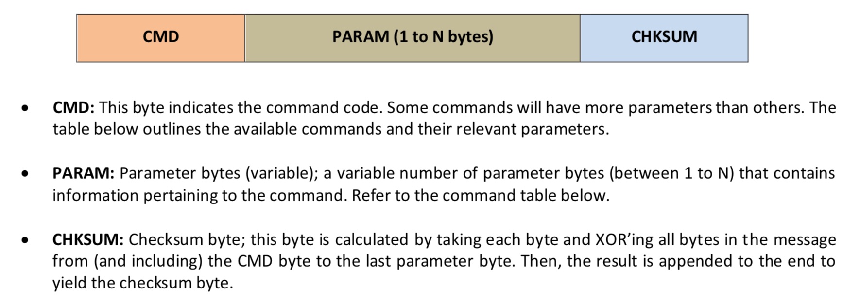

Format for serial communication between the programmable display and the host device, which could be a Biomaker Arduino , computer or Raspberry Pi. Each command is followed by an identifier for the target GUI widget, parameters and checksum.
Max Danilin and Victor Nakoryakov, XOD developers, haved helped with the development of XOD nodes for touchscreen support (https://forum.xod.io/t/visi-genie-library-to-work-with-4d-ulcd-displays/1625) - to allow simple programming of sophisticated interfaces and communication with Arduino-controlled hardware, using XOD nodes. (Check out https://youtu.be/9Nm_3ucTNcM for a video summary of the type of outcomes one can expect). The draft XOD library can be found at: https://xod.io/libs/gabbapeople/4d-ulcd/. It provides a library to work with gen4-µLCD-DT display modules by 4D Systems. This library provides graphical nodes for basic operations with common ViSi-Genie objects of the 4D Systems workshop IDE - and allows simple programming of user interface interactions.
read-dip-switch: Reads a value from a genie "DIP SWITCH" object
read-knob: Reads a value from a genie "KNOB" object
read-rocker-switch: Reads a value from a genie "ROCKER SWITCH" object
read-rotary-switch: Reads a value from a genie "ROTARY SWITCH" object
read-slider: Reads a value from a genie "SLIDER" object
read-trackbar: Reads a value from a genie "TRACKBAR" object
read-winbutton: Reads a value from a genie "WINBUTTON" object
write-angular-meter: Writes an integer value to a genie "ANGULAR METER" object
write-cool-gauge: Writes an integer value to a genie "COOL GAUGE" object
write-custom-digits: Writes an integer value to a genie "CUSTOM DIGITS" object
write-led: Writes an integer value to a genie "LED" object
write-led-digits: Writes an integer value to a genie "LED DIGITS" object
write-meter: Writes an integer value to a genie "METER" object
write-tank: Writes an integer value to a genie "TANK" object
write-user-led: Writes an integer value to a genie "USER LED" object
init: Initializes a 4D uLCD device with custom settings
The Arduino device and the touchscreen are connected via an Arduino shield, and communication is established by seting up a serial port connection throught the UART node. The 4D-µLCD nodes can then be used read and write data to the screen elements. For example, inputs from switches and knobs can be used to animate on-screen indicators and gauges. Most of the animated interactions are handled directly by the display processor and the ViSi-Genie-Genie programmed elements (for example, graphical responses to touching an on-screen switch).


Additional software and technical resources:
4D Maker projects
See a collection of documented projects using 4D Systems hardware at www.hackster.io:
(https://www.hackster.io/4DMakers)
Hardware suppliers:
4D Systems Gen4 µLCD 3.2” resistive touch screen:
Current Price: around £50/$70 per kit
RS online: https://uk.rs-online.com/web/p/lcd-colour-displays/12580202
International distributors
https://www.4dsystems.com.au/distributors