
16x2 LCD Screen (TZT 1602LCD green)
Summary
The Biomaker Stage-2 component pack contains a liquid crystal display (LCD) capable of displaying 2 lines of 16 characters (right). The device is equipped with an I2C interface backpack, that allows serial communication with the device. (This is the black-coloured circuit board soldered to the back of the green-coloured LCD board). The I2C interface allows communication with the LCD screen through two wires plus power supply, rather than 8+ wires required by a parallel port device. The I2C protocol allows comunication with multiple devices on the same 2 wire bus. Each device needs a unique address, usually set in the hardware.
The LCD display is powered by a 5V supply and draws about 25mA with the backlight on, and 2mA without. The green coloured backlight sits behind black coloured characters. The characters are formed in two lines of 16 characters in 5x7 dot matrices.
The display should be connected to the microcontroller via the Vcc (5V), Gnd (ground), SDA (data) and SCL (clock) wires. Because it is common to use multiple I2C devices, it is generally easier to connect through the breadboard, which allows multiple devices to share the I2C signals and power from the relevant sockets on the yellow connector on the microcontroller board.
XOD provides the software node text-lcd-16x2-i2c, that allows direct communication with the display, with inputs for each line of the display (see below). The address of the i2C device should be set at 27h using the ADDR parameter.
The text display can be a very useful tool for following program behaviour. In addition, XOD provides the watch node, a number of which can be connected to the outputs of key nodes, and provide real-time output of values as a programme is run in debug mode.
Advanced use: If you which to use multiple LCD displays on the I2C bus, you can add solder bridges to the jumpers A0, A1 and A2 on the I2C backpack - in order to change the address of each device, and allow them to be individually addressed. The supplied I2C backpack has a PCF8574T chip: and the IC address is (high order first) 0100 A2 A1 A0. When shipped, A2~A0 are all vacant. The default I2C address therefore: 0100 111 (0x27). If you want to modify the address yourself add the relevant jumpers, noting that floating address pad is 1, and the short circuit is 0 after adding a solder bridge.
Important: There is a potentiometer that controls the contrast setting of the display. It is a controlled by a black plastic wheel at the front left edge of the LCD screen. (Contrast can also be adjusted using the blue potentiometer on the I2C backpack). The contrast setting requires fine adjustment, and the screen will appear blank and unresponsive if badly adjusted. If, on first use, you want to check that the LCD screen is correctly connected (i.e. are using the correct I2C address), use a XOD node to switch the backlight on and off. If that works, load some text into the screen, and adjust the contrast for best legibility.


How to Connect
To connect to the Grove Beginner Kit board:
(optional) Attach the LCD display module to the plastic mounting sheet on the Totemmaker stand. For example, 3x M3 bolts and stand-offs will work well - or you can use stick-down velco or other temporary measures.
Use Dupont cables to connect the SDA, SCL, 5V and GND signals on the main yellow connector for the Arduino-compatible microcontroller - to the mini breadboard. Use connected sockets on the breadboard to further connect to the 4 pins on the I2C backpack of the LCD display.
Wiring diagram for connecting the 1602 LCD display
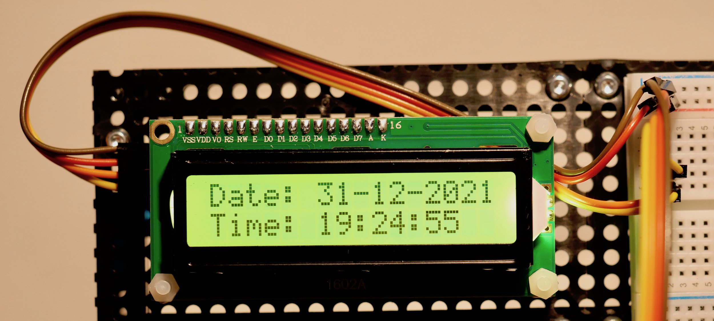
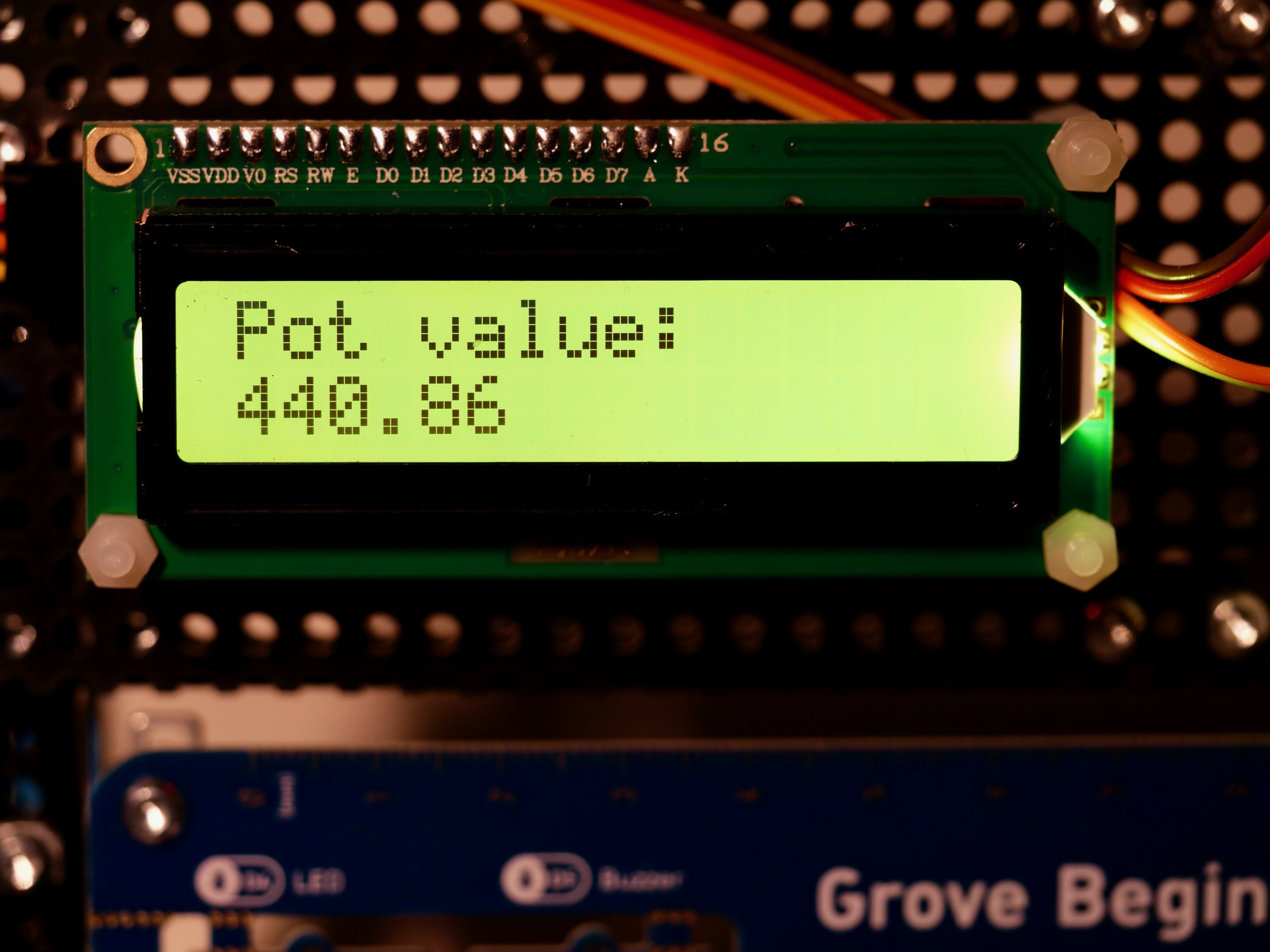
Example of the 1602 LCD screen display when working
Connections on the main Arduino UNO compatible section of the board
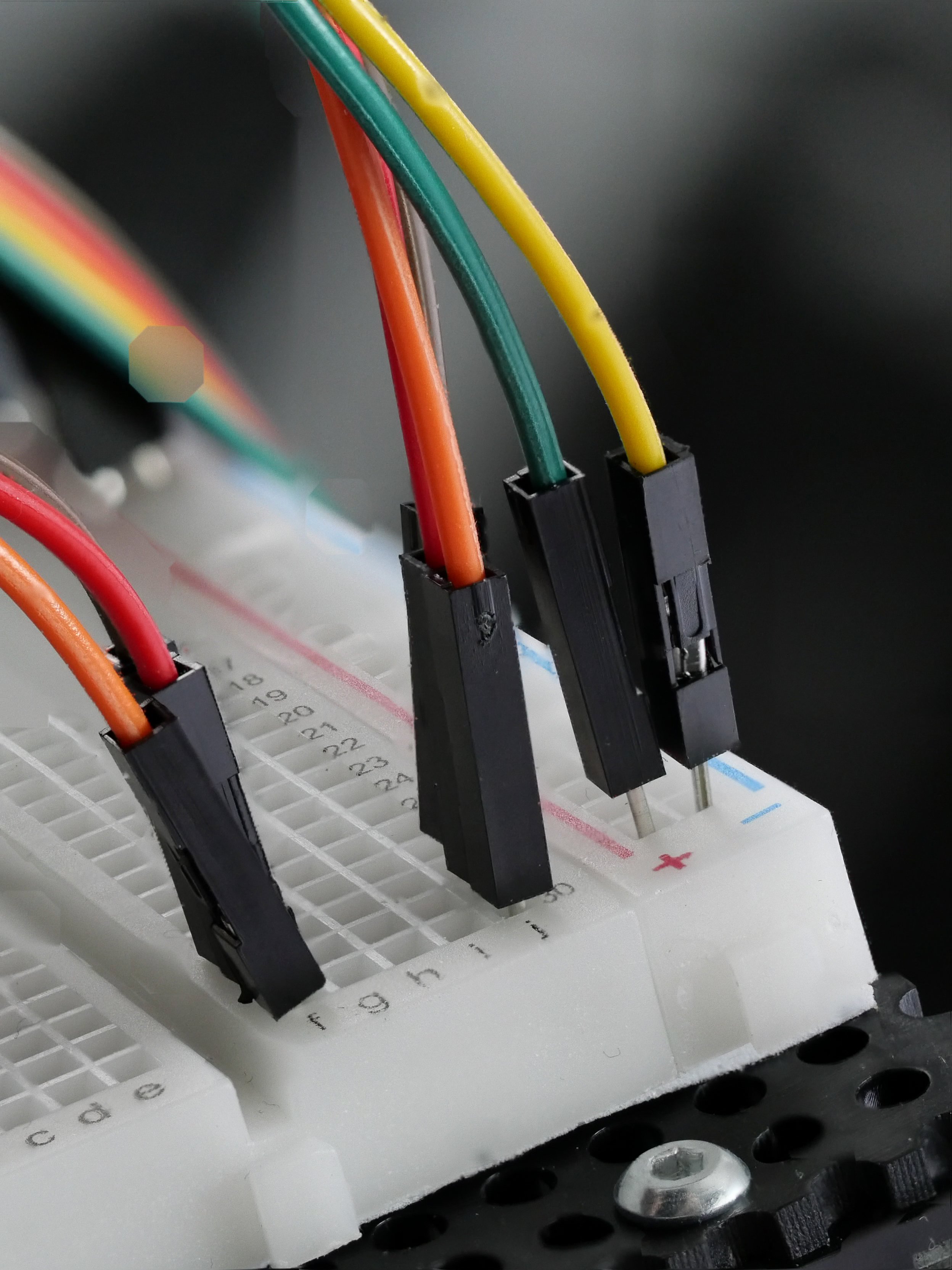
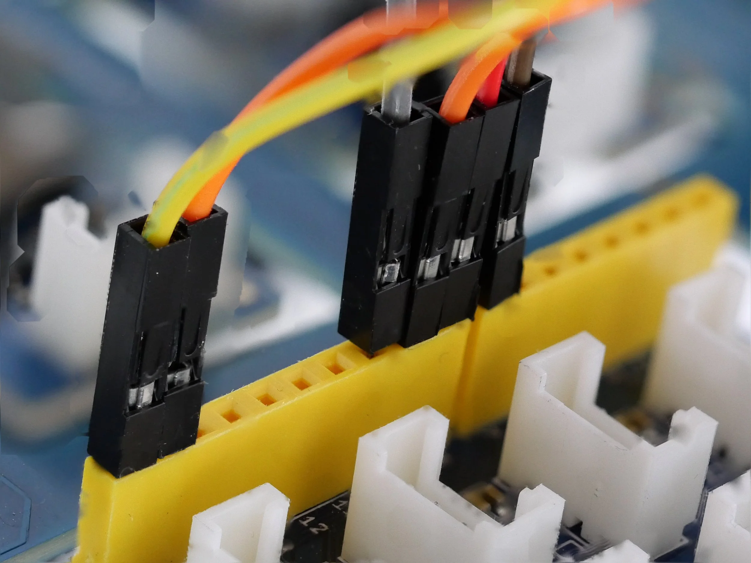
Connections on the breadboard
How to Use in XOD
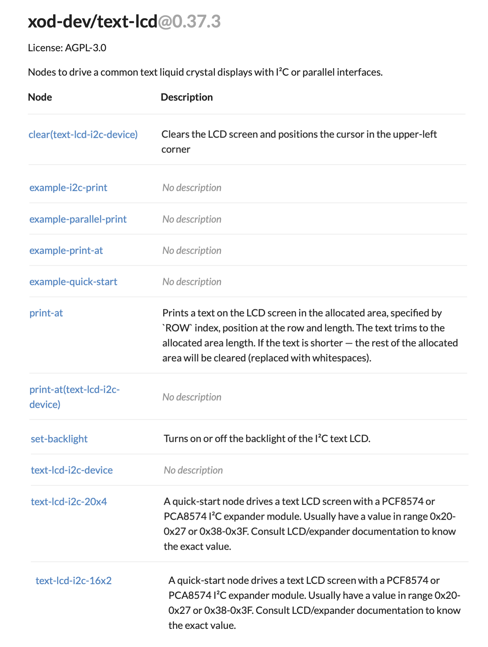
XOD provides a standard library (xod-dev/text-lcd) to drive the screen. This includes useful nodes like text-lcd-i2c-16x2 for directly displaying text, as well as other specialised nodes and examples (right).
Scroll down the XOD user interface to find the xod-dev/text-lcd library, open and identify the text-lcd-16x2-i2c node and drag onto the work area. The node allows setting parameters for the screen, and feeding data to the display.
(The node provides the code necessary to drive a text LCD screen with a PCF8574 or PCA8574 I2C expander module. Usually have a value in range 0x20-0x27 or 0x38-0x3F. Consult LCD/expander documentation if you want to use a different LCD display and need to know the exact value. Also, Cesar Sosa has provided a simple XOD patch that can be used to scan the I2C bus for connected devices: https://forum.xod.io/t/scanner-device-i2c/1490, and can be loaded as a XOD library cesars/i2c-scanner)
A simple way of testing the connected display is to add xod/core/constant-string nodes, and use these to feed text to the L1 and/or L2 input ports of the text-lcd-16x2-i2c node. An example is shown below that displays the 2-line message “Hello” “World”.
Some additional instructions on how to use the LCD screen with XOD and differnt Arduino hardware are available in the Biomaker 2019/20 Handbook - Chapter 6: Handling Simple Input Output Devices.

XOD NODE inputs:
ADDR: byte (I²C address of the expander chip, 27h for this device)
BL: boolean (Turns the backlight on and off)
L1: string (Add text for the first line here)
L2: string (Add text for the second line here)
ACT: pulse (Triggers activation of a new write event)
XOD node outputs:
Ack: pulse (Fires a pulse when the write event is finished)
Test patch:
A potentiometer is provided on the Grove Beginner Kit board, connected to port A0. The pot node can be set to this port and provide a user-generated variable signal for input to other nodes.
The output of the pot node can be fed to a map node. This allows the user to set the range of numbers that are tranversed when the potentiometer knob is turned. The output from pot node ranges from 0 to 1, and this can be mapped to a arbitrary range. In the example below, this is mapped to between 0 and 1000. The numerical output from the map node can be fed directly into an input for the text-lcd-i2c-16x2 node. In the example, this is fed to the second line of the display (L2). The inputs will accept a text string or number.
The text-lcd-16x2-i2c node provides inputs for the two lines of display (L1 and L2), with up to 16 characters allowed for each line. A text-node can be used to provide a fixed text string as a label for the other line of the display. In addition, the xod/core/concat node can be used to concatenate multiple inputs, including fixed labels and changing values - and provide output strings for display. Various format nodes (e.g. xod/core/format-number) can be used to adjust data values before display.

Notes
Working with text displays: https://xod.io/docs/guide/text-lcd/
Code-free menu generation using XOD and an LCD display: https://create.arduino.cc/projecthub/MattyZ/code-free-lcd-menu-generation-using-xod-582d36
I2C communication basics: https://xod.io/docs/guide/i2c/
Technical Specs
Datasheet